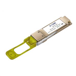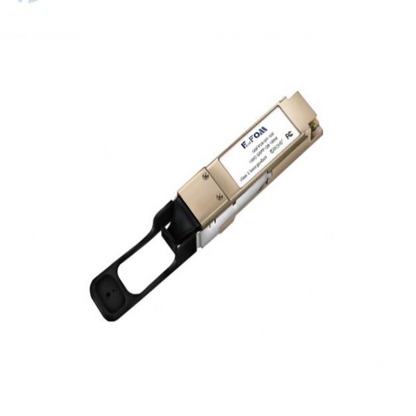
100Gb/s QSFP28 LR4 Transceiver
- Description
- Inquiry
100G Transceiver QSFP28 LR4 Fiber optical module cisco qsfp 100g
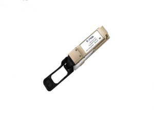
QSFP28 LR4 100G transceiver cisco qsfp 100g
PRODUCT FEATURES
- Compliant with 100GBASE-LR4
- Support line rates from 103.125 Gbps to 111.81 Gbps
- Integrated LAN WDM TOSA / ROSA for up to 10 km reach over SMF
- Digital Diagnostics Monitoring Interface
- Duplex LC optical receptacle
- No external reference clock
- Electrically hot-pluggable
- Compliant with QSFP28 MSA with LC connector
- Case operating temperature range:0°C to 70°C
- Power dissipation < 3.5 W
APPLICATIONS
- 100G Ethernet & 100GBASE-LR4 cisco qsfp 100g
STANDARD
- Compliant to IEEE 802.3ba, IEEE 802.3bm and 100G LR4
- Compliant to SFF-8436
- RoHS Compliant.
General Description
100G Transceiver integrates receiver and transmitter path on one module. In the transmit side, four lanes of serial data streams are recovered, retimed, and passed to four laser drivers. The laser drivers control 4- Distributed Feedback Laser (DFB) with center wavelength of 1296 nm, 1300nm, 1305nm and 1309 nm. The optical signals are multiplexed to a single –mode fiber through an industry standard LC connector. In the receive side, the four lanes of optical data streams are optically de-multiplexed by the integrated optical de-multiplexer. Each data stream is recovered by a PIN photo-detector and trans-impedance amplifier, retimed. This module features a hot-pluggable electrical interface, low power consumption and MDIO management interface.
100G Transceiver is designed with form factor, optical/electrical connection and digital diagnostic interface according to the QSFP28 Multi-Source Agreement (MSA) and compliant to IEEE 802.3bm.cisco qsfp 100g
Ⅰ Absolute Maximum Ratings
| Parameter | Symbol | Min. | Typ. | Max. | Unit | Note |
| StorageTemperature | Ts | -40 | – | 85 | ºC | |
| RelativeHumidity | RH | 5 | – | 95 | % | |
| PowerSupplyVoltage | VCC | -0.3 | – | 4 | V | |
| SignalInputVoltage | Vcc-0.3 | – | Vcc+0.3 | V |
Ⅱ Recommended Operating Conditions
| Parameter | Symbol | Min. | Typ. | Max. | Unit | Note |
| CaseOperatingTemperature | Tcase | 0 | – | 70 | ºC | Withoutairflow |
| PowerSupplyVoltage | VCC | 3.13 | 3.3 | 3.47 | V | |
| PowerSupplyCurrent | ICC | – | 1060 | mA | ||
| DataRate | BR | 25.78125 | Gbps | Eachchannel | ||
| TransmissionDistance | TD | – | 10 | km | ||
| Coupledfiber | Singlemodefiber | 9/125umSMF | ||||
Ⅲ Optical Characteristics
| Parameter | Symbol | Min | Typ | Max | Unit | NOTE |
| Transmitter | ||||||
| WavelengthAssignment | λ0 | 1294.53 | 1295.56 | 1296.59 | nm | |
| λ1 | 1299.02 | 1300.05 | 1301.09 | nm | ||
| λ2 | 1303.54 | 1304.58 | 1305.63 | nm | ||
| λ3 | 1308.09 | 1309.14 | 1310.19 | nm | ||
| TotalOutput.Power | POUT | 10.5 | dBm | |||
| AverageLaunchPowerPerlane | -4.3 | 4.5 | dBm | |||
| SpectralWidth(-20dB) | σ | 1 | nm | |||
| SMSR | 30 | dB | ||||
| OpticalExtinctionRatio | ER | 4 | dB | |||
| AveragelaunchPoweroffperlane | Poff | -30 | dBm | |||
| RIN | RIN | -128 | dB/Hz | |||
| OutputEyeMaskdefinition{X1,X2,X3,Y1,Y2,Y3} | {0.25,0.4,0.45,0.25,0.28,0.4} | |||||
| Receiver | ||||||
| RxSensitivityperlane | RSENS | -10.6 | dBm | 1 | ||
| LOSDe-Assert | LOSD | -30 | dBm | |||
| LOSAssert | LOSA | -12 | dBm | |||
| InputSaturationPower(Overload) | Psat | 4.5 | dBm | |||
| ReceiverReflectance | Rr | -26 | dB |
Notes:
- Measured with a PRBS 231-1 test pattern, @25.78Gb/s, BER<10-12 .
IV Electrical Characteristics
| Parameter | Symbol | Min | Typ | Max | Unit | NOTE |
| SupplyVoltage | Vcc | 3.13 | 3.3 | 3.47 | V | |
| SupplyCurrent | Icc | 1060 | mA | |||
| Transmitter | ||||||
| Inputdifferentialimpedance | Rin | 100 | Ω | 1 | ||
| Differentialdatainputswing | Vin,pp | 180 | 1000 | mV | ||
| TransmitDisableVoltage | VD | Vcc–1.3 | Vcc | V | ||
| TransmitEnableVoltage | VEN | Vee | Vee+0.8 | V | 2 | |
| Receiver | ||||||
| Differentialdataoutputswing | Vout,pp | 300 | 850 | mV | 3 | |
| LOSFault | VLOSfault | Vcc–1.3 | VccHOST | V | 4 | |
| LOSNormal | VLOSnorm | Vee | Vee+0.8 | V | 4 |
Notes:
- Connected directly to TX data input pins. AC coupled thereafter.
- Or open circuit.
- Into 100 ohms differential termination.
- Loss Of Signal is LVTTL. Logic 0 indicates normal operation; logic 1 indicates no signal detected.
40G module
QSFP+ LR4
QSFP+ transceiver
100G transceiver
QSFP28 SR4 transceiver
QSFP28 LR4 transceiver
CFP transceiver
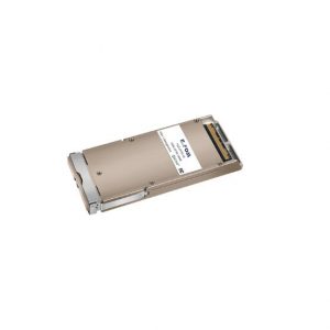
CFP2 transceiver
CFP4 transceiver
PDH Multiplexer
SDH Multiplexer
E1 Converter
TDM over IP
Modem
PCM Multiplexer
Fiber Media Converter
Fiber Video Converter
SFP fiber module
Ultra Low Temperature Freezer
Speed Reducer
Rehabilitation Equipment
Fiber Optical Multiplexer
Related Products
40G QSFP+ transceiver
40G QSFP+ transceiver
QSFP+ SR fiber module
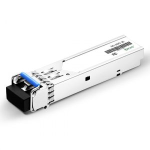
2.5G SFP transceiver,SM
SFP+ Transceiver,10Gbps 1310nm 10Km
SFP+ Transceiver,10Gbps 1310nm 10Km
1.25G BIDI SFP module,20KM,single fiber SFP transceiver
1.25G BIDI SFP module,20KM,single fiber SFP transceiver
2.5G SFP transceiver multi mode
SFP transceiver,2.5G,MM
100G QSFP28 SR4 transceiver
SFP+ Transceiver,10Gbps 1310nm 40Km
SFP+ Transceiver,10Gbps 1310nm 40Km
1.25G SFP fiber module,MM,850nm
1.25G SFP fiber module,MM,850nm
40G QSFP+ LR4 transceiver switch qsfp+
40G QSFP+ LR4 transceiver
single mode QSFP+ LR4 fiber module
100Gb/s CFP2 LR4 Optical Transceiver
100G CFP2 Transceiver