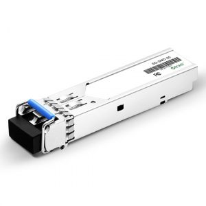
SFP+ Transceiver,10Gbps 1310nm 10Km
SFP+ Transceiver,10Gbps 1310nm 10Km
- Description
- Inquiry
10Gbps 1310nm SFP+ Transceiver, 10Km SFP+ Transceiver
1.Feature
l SFP+ Transceiver package with LC connector
l SFP+ Transceiver 1310nm DFB Laser and PIN photo detector
l Up to 10km transmission on SMF
l Power dissipation < 1W
l LVPECL compatible data input/output interface
l Low EMI and excellent ESD protection
l laser safety standard IEC-60825 compliant
l Compatible with RoHS
l Compatible with SFF8472
2.Application
l Ethernet
l Fiber Channel
3.Absolute Maximum Ratings
Parameter | Symbol | Minimum | Maximum | Units |
| Storage Temperature | Tst | -40 | +85 | °C |
| Supply Voltage | Vcc | 0 | +3.6 | V |
| Operating Relative Humidity | RH | 0 | 85 | % |
4.Operation Environment
Parameter | Symbol | Min | Typical | Max | Units | |
| Supply Voltage | Vcc | 3.15 | 3.45 | V | ||
| Operating Case Temperature | Commercial | Tc | -5 | +70 | °C | |
| Power Dissipation | 1 | W | ||||
| Data Rate | 10.3125 | Gbps | ||||
5.Optical Characteristics
(Ambient Operating Temperature -5°C to +70°C, Vcc =3.3 V)
Parameter | Symbol | Min. | Typ. | Max. | Units |
Transmitter Section | |||||
| Center Wavelength | lo | 1290 | 1310 | 1330 | nm |
| Side-Mode Suppression Ratio | SMSR | 35 | – | – | dB |
| Average Output Power | Po | -8 | – | +0.5 | dBm |
| Extinction Ratio | Er | 3.5 | – | – | dB |
| Dispersion Penalty | 3.2 | dB | |||
| Relative Intensity Noise | RIN12OMA | -128 | dB/Hz | ||
| Total jitter | Tj | IEEE 802.3ae | |||
Receiver Section | |||||
| Center Wavelength | lo | 1310 | nm | ||
| Receiver Sensitivity | Rsen | -12.5 | dBm | ||
| Stressed Sensitivity | Rsen | -10.5 | dBm | ||
| Receiver Overload | Rov | 0 | dBm | ||
| Return Loss | 12 | dB | |||
| LOS Assert | LOSA | -20 | dBm | ||
| LOS Dessert | LOSD | -17 | dBm | ||
| LOS Hysteresis | 0.5 | 4 | |||
6.Electrical Characteristics
(Ambient Operating Temperature -5°C to +70°C, Vcc =3.3 V)
Parameter | Symbol | Min. | Typ. | Max. | unit | |
Transmitter Section | ||||||
| Input Differential Impendence
| Zin | 90 | 100 | 110 | Ohm | |
| Data Input Swing Differential | Vin | 180 | 700 | mV | ||
| TX Disable | Disable | 2.0 | Vcc | V | ||
| Enable | 0 | 0.8 | V | |||
| TX Fault | Assert | 2.0 | Vcc | V | ||
| Deassert | 0 | 0.8 | V | |||
Receiver Section | ||||||
| Output differential impendence | Zout | 100 | Ohm | |||
| Data output Swing Differential | Vout | 300 | 800 | mV | ||
| Rx_LOS | Assert | 2.0 | Vcc | V | ||
| Deassert | 0 | 0.8 | V | |||
7.Diagnostics
Parameter | Range | Accuracy | Unit | Calibration |
| Temperature | -10 ~ 75 | ±3 | ºC | Internal |
| Voltage | 0 ~ VCC | 0.1 | V | Internal |
| Bias Current | 0 ~ 100 | 0.5 | mA | Internal |
| Tx Power | -8 ~ 1 | ±1 | dBm | Internal |
| Rx Power | -18 ~ 0 | ±1 | dBm | Internal |
8.EEPROM INFORMATION(A0)
| Addr | Field Size (Bytes) | Name of Field | HEX | Description |
| 0 | 1 | Identifier | 03 | SFP |
| 1 | 1 | Ext. Identifier | 04 | MOD4 |
| 2 | 1 | Connector | 07 | LC |
| 3-10 | 8 | Transceiver | 10 00 00 00 00 00 00 00 | Transmitter Code |
| 11 | 1 | Encoding | 06 | 64B66B |
| 12 | 1 | BR, nominal | 67 | 10000M bps |
| 13 | 1 | Reserved | 00 | |
| 14 | 1 | Length (9um)-km | 0A | |
| 15 | 1 | Length (9um) | 00 | |
| 16 | 1 | Length (50um) | 00 | |
| 17 | 1 | Length (62.5um) | 00 | |
| 18 | 1 | Length (copper) | 00 | |
| 19 | 1 | Reserved | 00 | |
| 20-35 | 16 | Vendor name | 57 49 4E 54 4F 50 20 20 20 20 20 20 20 20 20 20 | |
| 36 | 1 | Reserved | 00 | |
| 37-39 | 3 | Vendor OUI | 00 00 00 | |
| 40-55 | 16 | Vendor PN | xx xx xx xx xx xx xx xx xx xx xx xx xx xx xx xx | ASC II |
| 56-59 | 4 | Vendor rev | 31 2E 30 20 | V1.0 |
| 60-61 | 2 | Wavelength | 05 1E | 1310nm |
| 62 | 1 | Reserved | 00 | |
| 63 | 1 | CC BASE | XX | Check sum of byte 0~62 |
| 64-65 | 2 | Options | 00 1A | LOS, TX_DISABLE, TX_FAULT |
| 66 | 1 | BR, max | 00 | |
| 67 | 1 | BR, min | 00 | |
| 68-83 | 16 | Vendor SN | 00 00 00 00 00 00 00 00 00 00 00 00 00 00 00 00 | Unspecified |
| 84-91 | 8 | Vendor date code | XX XX XX 20 | Year, Month, Day |
| 92-94 | 3 | Reserved | 00 | |
| 95 | 1 | CC_EXT | XX | Check sum of byte 64~94 |
| 96-255 | 160 | Vendor specific |
9.Pin Description
| Pins | Name | Discription | NOTE |
1 | VeeT | Transmitter Ground | |
2 | Tx Fault | Transmitter Fault Indication | 1 |
3 | Tx Disable | Transmitter Disable | 2 |
4 | MOD DEF2 | Module Definition 2 | 3 |
5 | MOD DEF1 | Module Definition 1 | 3 |
6 | MOD DEF0 | Module Definition 0 | 3 |
7 | RS0 | Not Connected | |
8 | LOS | Loss of Signal | 4 |
9 | RS1 | Not Connected | |
10 | VeeR | Receiver Ground | |
11 | VeeR | Receiver Ground | |
12 | RD- | Inv. Received Data Output | 5 |
13 | RD+ | IReceived Data Output | 5 |
14 | VeeR | Receiver Ground | |
15 | VccR | Receiver Power | |
16 | VccT | Transmitter Power | |
17 | VeeT | Transmitter Ground | |
18 | TD+ | Transmit Data Input | 6 |
19 | TD- | Inv. Transmit Data Input | 6 |
20 | VeeT | Transmitter Ground |
40G module
QSFP+ LR4
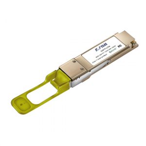
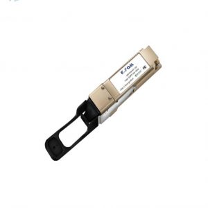
QSFP+ transceiver
100G transceiver
QSFP28 SR4 transceiver
QSFP28 LR4 transceiver
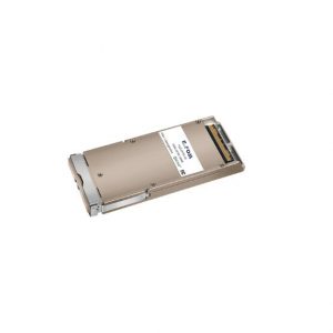
CFP transceiver
CFP2 transceiver
CFP4 transceiver
PDH Multiplexer
SDH Multiplexer
E1 Converter
TDM over IP
Modem
PCM Multiplexer
Fiber Media Converter
Fiber Video Converter
SFP fiber module
Ultra Low Temperature Freezer
Speed Reducer
Rehabilitation Equipment
Fiber Optical Multiplexer
Ultra Low Temperature Freezer
Rehabilitation Equipment
Fiber Optical Multiplexer
Speed Reducer
silicone oil
Related Products
SFP fiber module,1.25G,SM 1310nm,20KM
SFP fiber module,1.25G,SM 1310nm
2.5G SFP transceiver,SM
100Gb/s CFP2 LR4 Optical Transceiver
100G CFP2 Transceiver
100Gb/s QSFP28 LR4 Transceiver
40G QSFP+ transceiver
40G QSFP+ transceiver
QSFP+ SR fiber module
40G QSFP+ LR4 transceiver switch qsfp+
40G QSFP+ LR4 transceiver
single mode QSFP+ LR4 fiber module
SFP Transceiver,155M,SM 1310nm,20KM
SFP module,SFP transceiver,155M SM 1310nm
100G QSFP28 SR4 transceiver
1.25G BIDI SFP module,20KM,single fiber SFP transceiver
1.25G BIDI SFP module,20KM,single fiber SFP transceiver
SFP+ Transceiver,10Gbps 1310nm 40Km
SFP+ Transceiver,10Gbps 1310nm 40Km